VLAN ID naming schemes

Introduction

Naming schemes are hard. I don’t think anyone would argue with me on that. Whether they’re for domain names, hostnames, usernames, etc, coming up with one that is informative / standalone, intuitive, flexible, consistent, and future-proof within the restrictions of a system is easy to fail at, speaking from experience.

VLAN IDs are particularly tricky because:

  1. They’re purely numeric.

  2. They’re restricted to 0 – 4095. In practice, this is actually less. For example, Ubiquiti UniFi’s restrictions are 2 – 4009.

  3. They’re frequently displayed without context of the subnet that they’re assigned to and represent.

Tip: Throughout my years in IT, one thing I’ve learned is that networks will eventually include subnets that you didn’t account for.

When I was first tasked with setting up a network to support multiple clients’ existing and future subnets after realising the above, I researched publicly-accepted VLAN ID naming schemes but each that I found quickly fell apart for our usage.

So, to demonstrate the suitability of each VLAN ID naming scheme, I will be using the following subnets as examples:

  • 10.0.250.0/24

  • 172.16.250.0/24

  • 192.168.1.0/24

Accepted naming scheme #1: Sequential or random

I don’t think I need to spend long on this one. Obviously, you’d have to use some kind of reference material like a spreadsheet to know what VLAN ID corresponds to what subnet which is far from ideal.

Accepted naming scheme #2: Third octet

The rule of this naming scheme is just to use the third octet (section) of the subnet so let’s see how that works out:

Subnet VLAN ID Result
10.0.250.0/24 250 Fail: Collision with 172.16.250.0/24.
172.16.250.0/24 250 Fail: Collision with 10.0.250.0/24.
192.168.1.0/24 1 Fail: VLAN ID 1 is reserved as the default.

Accepted naming scheme #3: First octet + third octet

So, a workaround around to #2 is to append the third octet to the first octet so let’s see how that works out:

Subnet VLAN ID Result
10.0.250.0/24 10250 Fail: Too long.
172.16.250.0/24 172250 Fail: Too long.
192.168.1.0/24 1921 Pass.

My naming scheme

So, my naming scheme is RFC 1918 “private subnet” designation (10.*.*.*/8 = 1, 172.16.*.*/12 = 2, 192.168.*.*/16 = 3) + third octet so let’s see how that works out:

Subnet VLAN ID Result
10.0.250.0/24 1250 Pass.
172.16.250.0/24 2250 Pass.
192.168.1.0/24 31 Pass.

This one is almost everything I said in my first paragraph: informative / standalone, flexible, consistent, and future-proof.

Almost everything. Like everything in life, there are tradeoffs: You have to know the rule for it to be intuitive and it probably won’t work if you need literally thousands of VLANs in one location. But hey, it’s the least worst option.

I’ve never seen anyone else suggest anything like this before, hence this post.

Update 2020/07/24: Today, I was on a Juniper JNCIA-Junos certification training webinar and I was both surprised and happy to see that they seem to agree!

View fullsize

Ben Hooper - 2020-07-24 11-51-07.png


My subnetting scheme

While we’re on the subject of schemes that are easy to get wrong, I thought I’d share my personal subnetting scheme. I like to use 10.<location>.<network type>.<host>/24 with the third octet starting at 0 and increasing by multiples of 8. For example:

  • 10.0.0.0/24

  • 10.0.8.0/24

  • 10.0.16.0/24

  • 10.0.232.0/24

  • 10.0.240.0/24

  • 10.0.248.0/24

The benefits of this are as follows:

  1. It’s scalable and an efficient use of IP space because the third octet being seperated by multiples of 8 means that, if needed, the existing subnets’ prefixes / masks can be expanded into the gaps or new subnets can be inserted.

  2. When combined with my preferred VLAN ID naming scheme, the VLAN IDs will be consistent across sites because VLANs are restricted to layer 2 networks. This is great for centrally-managed Wi-Fi / SSIDs, manually tagged devices, etc.

Some examples of network types that I would always try to segment are as follows:

  • Systems management such as Out-of-Band Management (OOBM) / Lights-Out Management (LOM), routers, firewalls, jumpboxes, etc.

  • Domain Controllers.

  • General servers.

  • Printers.

  • Organisation-owned End User Devices (EUDs) such as desktop PCs, laptop PCs, tablet PCs, smartphones, Remote Desktop Session Host (RDSH) servers, etc.

  • Personal-owned and guest devices.

  • Payment terminals.

    etc

Below, I have created a diagram as a visualisation of all of this:

View fullsize

Subnet diagram (2020-04-25 13-50).png

Content retrieved from: https://mythofechelon.co.uk/blog/2019/6/27/vlan-id-naming-schemes.

Skripte über GPO mit Adminrechten ausführen

Besonders beim Automatisieren sind Skripte immer wieder hilfreich. Was aber nun, wenn man diese Skripte über eine Gruppenrichtlinie mit erhöhten Rechten ausführen möchte? Wer hier nicht aufpasst, tappt schnell in eine der klassischen Fallen der Gruppenrichtlinien-Verarbeitung. Nämlich dem Unterschied zwischen der Computer- und Benutzerkonfiguration innerhalb einer Richtlinie.

Vorm Anlegen der Richtlinie sollte man sich darüber im Klaren sein, auf welcher Ebene das Skript laufen soll. Also: Benutzer- oder Computerebene? Skripte auf Benutzerebene werden folgerichtig im Kontext des angemeldeten Benutzers ausgeführt und sind dann auch all dessen Einschränkungen unterworfen. Für benutzerspezifische Änderungen gut, sonst wahrscheinlich eher nicht.

Bindet man das Skript jedoch auf Computerebene ein, entfällt der Benutzerkontext und es erfolgt eine Ausführung mit administrativen Rechten. Quasi wie wenn man lokal eine Batch als Administrator ausführt. Um nun Skripte per GPO mit Adminrechten auszuführen, sind folgende Schritte notwendig:

GPO - Skripte Computer Admin
  1. Öffne in der Gruppenrichtlinien-Verwaltung den Gruppenrichtlinien-Editor der entsprechenden Richtlinie
  2. Suche dort den folgenden Pfad auf:
    Computerkonfiguration -> Windows-Einstellungen -> Skripts -> Starten
  3. Füge nun das gewünschte Skript hinzu
  4. Überprüfe abschließend die Richtlinienzuweisung und setze die Änderungen ggf. per gpupdate /force durch

Da die Richtlinie auf der Computerebene greift, wirkt sie natürlich ohne weitere Vorkehrungen nur auf Computer-Objekte im AD. Wer also die GPO auch auf Benutzerobjekte wirken lassen möchte, muss vorher die Loopback-Verarbeitung aktivieren.

Damit sind dann hoffentlich alle Unwägbarkeiten aus dem Weg geräumt. Die in der Computerkonfiguration der Richtlinie eingebundenen Skripte sollten nach einer Aktualisierung der wirkenden Richtlinien beim nächsten PC-Start mit administrativen Rechten ausgeführt werden.

Content retrieved from: https://dashdot.de/2019/01/18/skripte-gpo-admin/.

Auf Client wirkende Gruppenrichtlinien anzeigen lassen

In größeren Active Directory-Infrastrukturen kann die Ordnung der Gruppenrichtlinien schnell verloren gehen. Dies erschwert unter Umständen die Fehlerbehebung, wenn es zu Problemen kommt. Um bei der Recherche trotzdem schnell einen Überblick über die auf einen Client wirkenden GPOs zu erhalten, gibt es diverse Tools, mit denen man die aktiven Gruppenrichtlinien anzeigen lassen kann.

Variante 1: gpresult

Die gängigste Variante der Auswertung ist heutzutage gpresult. Mit diesem Helferlein sieht man recht schnell und übersichtlich, welche aktiven Gruppenrichtlinien auch aktuell greifen. Für dieses Tool gibt es einige verschiedene Ausgabemöglichkeiten, die ich hier mal kurz darstelle.

Ergebnisse in Kommandozeile anzeigen lassen

Das ist der schnellste Weg, um direkt in der Konsole einen Überblick über die wirkenden GPOs zu erhalten. Außerdem erhält man noch weitere Informationen, wie zum Beispiel den Zeitpunkt des letzten Updates, den dabei genutzten Domänen-Controller oder etwaige Gruppenmitgliedschaften. Dafür muss man lediglich den folgenden Befehl absetzen:
gpresult /r

Auswertung auf Computerkonfiguration beschränken

Zur Übersichtlichkeit kann man die Ausgabe auch einschränken, zum Beispiel auf die Richtlinien der Computerkonfiguration. Dazu hängt man einfach ein /scope:computer ran:
gpresult /r /scope:computer

Auswertung auf Benutzerkonfiguration beschränken

Das Gleiche geht natürlich auch für die Benutzerebene:
gpresult /r /scope:user

Remote-Computer abfragen

Auch ganz praktisch: Man kann die Anfrage ebenso an einen entfernten Computer schicken. Dies geschieht durch folgendes Kommando (%PC-NAME% entsprechend abändern):
gpresult /s %PC-NAME% /r

Ergebnisse in Datei exportieren

Wem jetzt allerdings die Kommandozeile etwas zu unübersichtlich ist, dem empfehle ich den Export der Ergebnisse in eine externe Datei. Dafür gibt es diverse Möglichkeiten.

TXT-Datei

Wer’s simpel mag, kann hier zur guten alten Text-Datei greifen. Dafür braucht es den folgenden Befehl:
gpresult /r >C:GPOs.txt

HTML-Datei

Wer jedoch lieber eine grafische Übersicht möchte, sollte auf eine HTML- oder XML-Datei zurückgreifen. Für einen HTML-Export sieht das Kommando wie folgt aus:
gpresult /h C:GPOs.html

XML-Datei

Wer stattdessen zum XML-Export tendiert, muss nicht viel anpassen:
gpresult /x C:GPOs.xml

Detaillierte Informationen ausgeben lassen

Abschließend noch ein kleiner Tipp aus den Kommentaren (danke): Mit dem Parameter /z lassen sich detailliertere Ergebnisse generieren, für komplexere Probleme:
gpresult /z

Variante 2: rsop

Die rsop-Konsole ist schon etwas in die Jahre gekommen, kann sich im Einzelfall aber trotzdem noch als nützlich erweisen, um zu sehen, welche Optionen einer GPO greifen. Im Gegensatz zu gpresult werden die Ergebnisse in einem vom Gruppenrichtlinienen-Editor bekannten Fenster dargestellt. Es gibt allerdings zwei entscheidende Nachteile: Man muss sich zu jeder einzelnen Option durchklicken, um nachzuschauen, wie diese eingestellt ist. Es gibt also keine Übersicht. Zudem werden die Einträge der Rubrik Windows-Einstellungen einer GPO nicht ausgewertet. Wer rsop trotzdem eine Chance geben möchte, gibt folgendes in der Kommandozeile oder im Ausführen-Dialog ein:
rsop.msc
Mit dieser letzten Möglichkeit haben wir jetzt die gängigsten Optionen abgedeckt, um Gruppenrichtlinien anzeigen zu lassen. Es sei denn, jemanden fällt hier noch eine ein. Abschließend sei noch auf die Microsoft Docs verwiesen, wo alle Schalter für gpresult aufgeführt sind.

Content retrieved from: https://dashdot.de/2021/04/08/auf-client-wirkende-gruppenrichtlinien-anzeigen-lassen/.

Aktivieren von IPv6-DHCP Server in einer Domäne

  1. netsh int ipv6 Show int
    dort die Nummer bei Idx für die Netzwerkkarte notieren
  2. netsh int ipv6 set int advertise=enabled
  3. netsh int ipv6 set route fc00:1192:1168:1178::/64 „<Name der Netzwerkkarte“ publish=yes

Nicht notwendig, wenn der Router korrekt konfiguriert ist (Schlagwort Router Advertising)

Ping in Windows erlauben:
GUI, PowerShell, netsh, GPO

Ping-Request mit ping.exeWindows blockiert Ping-Anforderungen durch eine ent­sprechende Konfigu­ration der Firewall. Diese Ein­stellung lässt sich auf mehrere Arten ändern, entweder über die grafische Konsole der Firewall, über die Kommando­zeile sowie PowerShell oder zentral über Gruppenrichtlinien.

Der Grund für das abweisende Verhalten von Windows gegenüber Ping-Requests sind Sicherheitsbedenken von Microsoft. Schließlich wird der Dienst gerne für Angriffe missbraucht, bevorzugt für Denial-of-Service-Attacken.

Änderung der Regeln nur als Administrator

Nichtsdestotrotz hat Ping nach wie vor seine Berechtigung als Diagnosewerkzeug bei Netzwerkproblemen, so dass man diese strikte Konfiguration der Firewall meistens lockern wird. In Firmennetzen kann man die damit verbundenen Risiken reduzieren, indem man die vordefinierte Firewall-Regel nur für das Profil Domäne aktiviert oder zulässige Anfragen auf bestimmte IP-Adressen beschränkt.

Für diesen Zweck stehen mehrere Werkzeuge zur Verfügung. Während Standardbenutzer die vorhandenen Einstellungen mit den Kommandozeilen-Tools ansehen können, setzt die Aktivierung von Firewall-Regeln grundsätzlich administrative Rechte voraus.

Eingehende Pings durchlassen

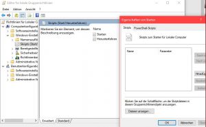
Das gängigste Programm zur Aktivierung der Firewall-Regeln für eingehende Pings ist die grafische Oberfläche Windows-Firewall mit erweiterter Sicherheit. Hier muss man sich als Administrator anmelden, um überhaupt die Einstellungen angezeigt zu bekommen.

Die Firewall-Regel für eingehende Ping-Anforderungen subsumiert Microsoft unter jenen für die Datei- und Druckerfreigabe.

Dort wechselt man in der linken Spalte zu Eingehende Regeln und sucht anschließend im Hauptfenster nach Datei- und Druckerfreigabe (Echo­anfor­derung – ICMPv4 eingehend). Diese Regel existiert in Ausprägungen für die Profile Domäne sowie für Öffentlich und Privat. Je nach Bedarf aktiviert man sie für ein bestimmtes oder für mehrere Profile (siehe dazu: Windows-Firewall: Regeln für Profile konfigurieren).

Zur Sicherheit lassen sich Ping-Anfragen auf bestimmte IP-Adressen und -Bereiche eingrenzen.

Öffnet man den Dialog Eigenschaften aus dem Kontextmenü dieser Regel, dann kann man dort unter Bereich => Remote-IP-Adresse die Clients, von denen Ping-Anfragen erlaubt sind, weiter einschränken. Existieren auf dem Rechner mehrere NICs, dann besteht zudem die Möglichkeit, über Lokale IP-Adressen jene festzulegen, zu denen Requests durchgelassen werden.

Ping zulassen mit PowerShell

PowerShell verfügt über eine Reihe von Cmdlets, mit denen sich die Firewall vollständig konfigurieren lässt. Für das Management der Regeln eignen sich Get-NetFirewallRule und Set-NetFirewallRule. Ersteres hilft dabei, den Status von Regeln zu ermitteln, Zweiteres kann diesen ändern.

Möchte man sich anzeigen lassen, welche Regeln für Ping zuständig sind, dann filtert man sie nach dem Begriff ICMP4:

Get-NetFirewallRule -name *ICMP4* | select name, DisplayName, Profile, Enabled | fl

Dieser Befehl gibt eine relative kurze Liste aus und zeigt unter anderem auch, für welches Firewall-Profil die Regeln gelten und ob sie aktiviert sind. Für eingehende Ping-Anforderungen in Domänen-Netzwerken ist demnach FPS-ICMP4-ERQ-In-NoScope zuständig, für die Profile Öffentlich und Privat hingegen FPS-ICMP4-ERQ-In.

Konfiguration der Firewall-Regeln für eingehende Pings mit PowerShell.

Nun kann man im nächsten Schritt die gewünschte Regel aktivieren, beispielsweise mit dem Befehl

Set-NetFirewallRule -name FPS-ICMP4-ERQ-In-NoScope -Enabled True -RemoteAddress 192.168.0.66

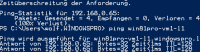
Er ändert nicht nur den Status der Regel FPS-ICMP4-ERQ-In-NoScope, so dass Ping-Anforderungen durchgelassen werden, sondern grenzt zusätzlich die zulässigen Hosts auf die IP-Adresse 192.168.0.66 ein. Vom Erfolg der Maßnahme kann man sich durch

Get-NetFirewallRule -name FPS-ICMP4-ERQ-In-NoScope | select name, enabled

überzeugen.

Firewall-Regel mit netsh.exe aktivieren

Wie schon in früheren Versionen von Windows steht auch weiterhin das Kommandozeilen-Tool netsh.exe für diese Aufgabe zur Verfügung. Zu seinen Nachteilen gehört nicht nur eine eigenwillige Syntax, sondern auch ein Mix aus übersetzten Namen für die Regeln und englischsprachigen Werten für die meisten Parameter.

Das netsh-Äquivalent zum obigen Aufruf von Set-NetFirewallRule würde so aussehen:

netsh advfirewall firewall set rule profile=Domain name=“Datei- und Druckerfreigabe (Echoanforderung – ICMPv4 eingehend)“ new enable=yes remoteip=192.168.0.66

Möchte man Anfragen von allen Rechnern zulassen, dann verzichtet man auf den Parameter remoteip. Will man hingegen die Regel für die Profile Öffentlich und Privat aktivieren, dann ändert man den Wert für profile auf Private,Public.

Ping erlauben über Gruppenrichtlinien

In zentral verwalteten Umgebungen wird man die Firewall-Einstellungen wahrscheinlich über GPOs konfigurieren wollen, beispielsweise für alle Rechner in einer bestimmten OU. Diese Möglichkeit bestand ebenfalls schon unter Windows 7 / 8.1, das Vorgehen ist dabei gleich geblieben. Siehe dazu meine Anleitung Ping mittels GPO erlauben in Windows 7 / 8.x und Server 2012 (R2).

Content retrieved from: https://www.windowspro.de/wolfgang-sommergut/ping-windows-10-erlauben-gui-powershell-netsh-gpo.

Subnetz- und CIDR-Rechner

Eingabe
IP-Adresse
Vorbelegen:
Subnetzmaske
 
Ausgabe
Byteformat
Binärformat
IP-Adresse
 
 
Subnetzmaske
 
 
Wildcardmaske
 
 
Netzadresse
 
 
Rechneradresse
 
 
Broadcastadresse
 
 
Bitanzahl der Net-ID
 
 
Bitanzahl der Host-ID
 
Anzahl IP-Adressen
 
Max. Zahl der Knoten
 
Erste IP-Adresse
 
Letzte IP-Adresse


Download: w-hermanns.de,

How To Set Up VLANs When You Don’t Understand VLANs

Several years ago, I needed to partition a network into separate VLANs.  The switches I had were capable, but I wasn’t.  I was having trouble understanding what the terms meant (Tagged, Untagged, Excluded) and how to configure each port to achieve my desired result.  I had trouble finding a good I-don’t-really-care-that-much-about-VLANS-or-Cisco-documentation-I-just-want-this-to-work-so-I-can-get-on-with-what-I-am-really-trying-to-do kind of explanation, so I thought I would write one.  Remember I said that was years ago?  My TODO list is very long.

The switches I was using in this project were Cisco/Linksys SGE2000P which is a “small business” switch.

VLAN concepts:

  1. VLANs are a way to group ports, potentially across multiple switches, into networks (Virtual Local Area Networks). In this way, a switch can be partitioned to, among other things, serve multiple networks all isolated from each other.
  2. Each VLAN is identified by an ID which is a number.
  3. Each port on the switch is designated as Tagged, Untagged or Excluded in each VLAN.
  4. If a port is Tagged, the switch will add the VLAN ID to the header of any packets sent on that interface.  Tagged packets are only understood by network equipment that is VLAN aware.
  5. If a port is Untagged the switch will not add the VLAN ID to the header of packets sent on that interface and will remove and VLAN IDs in packets that came in on a Tagged interface.
  6. If a port is Excluded from a VLAN packets with that VLAN ID will never be sent out on that port.
  7. If a port is marked Untagged on one VLAN, it will be excluded from all other VLANs.  In other words, an Untagged interface can only be a part of one VLAN at a time.
  8. A port can be marked as Tagged on any number of VLANs

What does all of that mean?

Any port that is going to carry traffic between 2 switches must be able to carry packets from all of the VLANs so therefore must be included in every VLAN that must transit that link.  The switch on the other end must be able to determine which VLAN to forward the packet to so the packets sent out that port must be tagged. It is also important that both switches understand VLANs.

Any port that is going to connect to a non-switch device must be marked untagged in the VLAN the device is supposed to be a part of.

Example

Say you want to create 3 different networks with 2 VLAN capable 16 port switches.  We’ll use VLAN IDs 7, 8, and 9.

We want to configure the networks thusly:

  • Connect port 16 on switch #1 to port 16 switch #2.  This cable will carry traffic from all 3 VLANs between the switches.  These ports must be tagged in all 3 VLANs
  • VLAN 7 will include ports 1, 2, and 3 on switch #1 and ports 1 and 2 on switch #2. These ports must be untagged on VLAN 7  and excluded from VLANs 8 and 9.
  • VLAN 8 will include ports 4 and 5 on switch #1 and ports 3, 4, and 5 on switch #2. These ports must be untagged on VLAN 8 and excluded from VLANs 7 and 9.
  • All other ports will be on VLAN 9. These ports must be untagged on VLAN 9 and excluded from VLANs 7 and 8.

So configure the ports like this:

Switch #1
Port VLAN 7 VLAN 8 VLAN 9
1 Untagged Excluded Excluded
2 Untagged Excluded Excluded
3 Untagged Excluded Excluded
4 Excluded Untagged Excluded
5 Excluded Untagged Excluded
6 Excluded Excluded Untagged
7 Excluded Excluded Untagged
8 Excluded Excluded Untagged
9 Excluded Excluded Untagged
10 Excluded Excluded Untagged
11 Excluded Excluded Untagged
12 Excluded Excluded Untagged
13 Excluded Excluded Untagged
14 Excluded Excluded Untagged
15 Excluded Excluded Untagged
16 Tagged Tagged Tagged


Switch #2
Port VLAN 7 VLAN 8 VLAN 9
1 Untagged Excluded Excluded
2 Untagged Excluded Excluded
3 Excluded Untagged Excluded
4 Excluded Untagged Excluded
5 Excluded Untagged Excluded
6 Excluded Excluded Untagged
7 Excluded Excluded Untagged
8 Excluded Excluded Untagged
9 Excluded Excluded Untagged
10 Excluded Excluded Untagged
11 Excluded Excluded Untagged
12 Excluded Excluded Untagged
13 Excluded Excluded Untagged
14 Excluded Excluded Untagged
15 Excluded Excluded Untagged
16 Tagged Tagged Tagged
 

Content retrieved from: https://www.megajason.com/2016/03/03/how-to-set-up-vlans-when-you-dont-understand-vlans/.

VMware iSCSI

Should I enable jumbo frames with iSCSI?

The general recommendation is to use the standard MTU of 1500 for iSCSI connectivity.

This recommendation is predicated upon several things:

  1. Simplicity. Enabling jumbo frames requires setting the proper MTU throughout the entire network. This means the vSphere Switch, vmkernel port (vmknic), physical NIC (pNIC), physical switches, routers (if routed iSCSI), and finally the FlashArray target ports. It is an all too common tale to see one or more of these components missed and thus problems with stability or performance are reported. 
  2. Not all environments benefit from jumbo frames. This was at one time a common (and rather heated) discussion in previous years. The anthem was almost always „jumbo frames enabled for best performance“. The reality though is actually based upon the workload between the initiators and target. If your applications / environment are consistently sending larger I/O requests than there is a good chance jumbo frames could help. How much will it help? Well, that answer can vary greatly so we won’t go into that here. The caveat though is that if the opposite is true (mostly smaller I/O requests), it can actually result in a performance penalty in your environment. If your host is waiting around to fill up a jumbo frame with smaller I/O requests then you are actually delaying transmission of your I/O and thus a slight performance penalty can be noted. How much? Again, it varies and isn’t the scope of this document.

The key takeaway here is know your environment. If you find jumbo frames are optimal for your environment please have all proper parties involved from end-to-end to ensure everything is implemented correctly.

If you decide to implement jumbo frames, the following command is vital to ensure you have properly configured your environment end-to-end:

vmkping -I <iscsi_vmk_interface> -d -s 8972 <ip_addr_of_target>

This ensures packets are not fragmented during the ping test (-d) and tests jumbo frames (-s 8972).

RTSP Stream als MJPEG in Netz streamen

http://192.168.x.xx:5000/webapi/entry.cgi?api=SYNO.SurveillanceStation.Stream.VideoStreaming&version=1&method=Stream&format=mjpeg&cameraId=xxxxxxxxxxxxxxxxxxxxxxxxxxxxxxxxxxx%22

Dazu geht man zunächst in die Einstellungen für die RTSP-Kamera und stellt die Kamera kurzeitig auf „MJPEG“ um. Der Stream wird dann in der Regel unterbrochen, aber das ist erst mal nicht weiter tragisch, da man am Ende wieder alles auf „H.264“ zurückstellt.

— Surveilance Station Camer Einstellungen

Nun klickt man mit der rechten Maustaste auf die betreffende Kamera und dann auf „Stream-Pfad freigeben“. Dann werden einem die Daten der Kamera, die man für die nachfolgenden Befehle benötigt, angezeigt. Neben der IP-Adresse der DiskStation (1) findet man hinter „cameraID=“ die wesentlichen ID-Daten der Kamera (2).

Mit folgendem Shellskript (Achtung: es dürfen keine CR am Zeilenende enthalten sein) kann man sich dann einen Snapshot holen.


#!/bin/bash

# +++++ Pfad und Name eines zu speichernden Bildes +++++
pictPath='/tmp/Bildname.jpg'

# +++++ Zugriffsdaten der Synology DiskStation +++++
ipDiskStation='xxx.xxx.xxx.xxx:5000' # IP:PORT der DiskStation
account='admin' # Admin-Name auf der DiskStation
password='xxxxxxxxxx' # Admin-Passwort
cameraId='xx&StmKey=xxxxxxxxxxxxxxxxxxxxxxxxx'

# +++++ Snaphshot holen +++++
wget -q --keep-session-cookies --save-cookies cookies.txt -O- "http://"$ipDiskStation"/webapi/entry.cgi?api=SYNO.API.Auth&version=3&method=login&account="$account"&passwd="$password

wget -q --load-cookies cookies.txt -O $pictPath "http://"$ipDiskStation"/webapi/entry.cgi?api=SYNO.SurveillanceStation.Camera&method=GetSnapshot&version=1&cameraId="$cameraId

exit 0

Siehe auch https://www.synology-forum.de/threads/rtsp-stream-als-mjpeg-in-netz-streamen.109971/

HP / Aruba Procurve 2530/2500 Default Management IP, Username/Passwrods and Configurations

HP / Aruba Procurve 2530/2500 Default Management IP, Username/Passwrods and Configurations

Back-up of an existing config

If you are performing a backup a config from another switch, two ways of downloading the configuration is through GUI and CLI (via TFTP)

via GUI: (System -> Updates/Download -> Configuration File (Highlight config name and click Download)

2018-02-20 16_47_16-HP 2530-24G-PoEP Switch (J9773A).png

via CLI. (you need to set up a TFTP server on a machine)

switch# copy running-config tftp <IP Address of the TFTP Server> filename.pcc

==============
Default Settings and Configurations of an Aruba/HP Procurve switch

In the factory default configuration, the switch has no IP (Internet Protocol) address and subnet mask, and no passwords. In this state, it can be managed only through a direct CONSOLE connection (How to connect to Console? Click here). To manage the switch through inband (networked) access, you should configure the switch with an IP address and subnet mask compatible with your network. Also, you should configure a Manager password to control access privileges from the console and Web browser interface.

IP-Address

HP ProCurve Switch 2524# configure
HP ProCurve Switch 2524(config)# vlan 1
HP ProCurve Switch 2524(vlan-1)# ip address 10.0.0.1 255.255.255.0
HP ProCurve Switch 2524(vlan-1)# wr mem
HP ProCurve Switch 2524(vlan-1)# exit
HP ProCurve Switch 2524(config)# exit
HP ProCurve Switch 2524#

(Basically, from here you can now set your machine’s IP into the same network above and access the GUI from your browser, otherwise, you can proceed with the other commands below)

Also, by default, as mentioned there is no username/password for the switch and you have to configure that manually through GUi or CLI below.

Configure VLANs

HP ProCurve Switch 2524# configure
HP ProCurve Switch 2524(config)# vlan 1
HP ProCurve Switch 2524(vlan-1)# name „Default“
HP ProCurve Switch 2524(vlan-1)# untag 2-6
HP ProCurve Switch 2524(vlan-1)# vlan 10
HP ProCurve Switch 2524(vlan-10)# name „First“
HP ProCurve Switch 2524(vlan-10)# untag 7-12
HP ProCurve Switch 2524(vlan-10)# vlan 20
HP ProCurve Switch 2524(vlan-20)# name „Second“
HP ProCurve Switch 2524(vlan-20)# untag 13-18
HP ProCurve Switch 2524(vlan-20)# exit
HP ProCurve Switch 2524(config)# exit
HP ProCurve Switch 2524#

Set up trunk ports

HP ProCurve Switch 2524# config
HP ProCurve Switch 2524(config)# trunk 23-24 trk1
HP ProCurve Switch 2524(config)# vlan 10
HP ProCurve Switch 2524(vlan-10)# tagged trk1
HP ProCurve Switch 2524(vlan-10)# vlan 20
HP ProCurve Switch 2524(vlan-20)# tagged trk1
HP ProCurve Switch 2524(vlan-20)# wr mem
HP ProCurve Switch 2524(vlan-20)# exit
HP ProCurve Switch 2524(config)# exit
HP ProCurve Switch 2524#

Disable all (but trunk) ports

HP ProCurve Switch 2524# configure
HP ProCurve Switch 2524(config)# int 2-22 disable
HP ProCurve Switch 2524(config)# wr mem
HP ProCurve Switch 2524(config)# exit
HP ProCurve Switch 2524#

Enable only necessary ports

HP ProCurve Switch 2524# configure
HP ProCurve Switch 2524(config)# int 2-4 enable
HP ProCurve Switch 2524(config)# int 13-15 enable
HP ProCurve Switch 2524(config)# wr mem
HP ProCurve Switch 2524(config)# exit
HP ProCurve Switch 2524#

Set up speed etc.

HP ProCurve Switch 2524# configure
HP ProCurve Switch 2524(config)# int 2-4 speed-duplex 100-full
HP ProCurve Switch 2524(config)# int 13-15 speed-duplex auto
HP ProCurve Switch 2524(config)# wr mem
HP ProCurve Switch 2524(config)# exit
HP ProCurve Switch 2524#

Set time and date

Time and date on hh:mm and mm:dd:yyyy format

HP ProCurve Switch 2524# configure
HP ProCurve Switch 2524(config)# time 10:05
Mon Jan 1 10:05:28 1990
HP ProCurve Switch 2524(config)# time 08/24/2010
Tue Aug 24 10:05:41 2010
HP ProCurve Switch 2524(config)# wr mem
HP ProCurve Switch 2524(config)# exit
HP ProCurve Switch 2524#

Set hostname

HP ProCurve Switch 2524# configure
HP ProCurve Switch 2524(config)# hostname „ServerRoom1“
ServerRoom1(config)# wr mem
ServerRoom1(config)# exit
ServerRoom1#

Backup settings

After running “sh run” copy/paste all between line which start with “hostname” to “ServerRoom1#” example to notepad and save that file.

ServerRoom1# sh run
ServerRoom1#

Restore settings from backup

All you have to do is copy/paste all (except the first “Running configuration:” line) to notepad on “Backup settings” part to “HP ProCurve Switch 2524#”.
If you have set operator and/or manager passwords, don’t copy/paste the lines which start with password.

HP ProCurve Switch 2524# configure
HP ProCurve Switch 2524(config)#

Set manager and operator password

ServerRoom1# configure
ServerRoom1(config)# password all
New password for Operator: ********
Please retype new password for Operator: ********
New password for Manager: ********
Please retype new password for Manager: ********
ServerRoom1(config)#

Content retrieved from: https://marktugbo.com/2018/02/20/hp-aruba-procurve-2530-2500-default-configurations/.

Betrieben von WordPress | Theme: Baskerville 2 von Anders Noren.

Nach oben ↑