VLAN ID naming schemes

Introduction

Naming schemes are hard. I don’t think anyone would argue with me on that. Whether they’re for domain names, hostnames, usernames, etc, coming up with one that is informative / standalone, intuitive, flexible, consistent, and future-proof within the restrictions of a system is easy to fail at, speaking from experience.

VLAN IDs are particularly tricky because:

  1. They’re purely numeric.

  2. They’re restricted to 0 – 4095. In practice, this is actually less. For example, Ubiquiti UniFi’s restrictions are 2 – 4009.

  3. They’re frequently displayed without context of the subnet that they’re assigned to and represent.

Tip: Throughout my years in IT, one thing I’ve learned is that networks will eventually include subnets that you didn’t account for.

When I was first tasked with setting up a network to support multiple clients’ existing and future subnets after realising the above, I researched publicly-accepted VLAN ID naming schemes but each that I found quickly fell apart for our usage.

So, to demonstrate the suitability of each VLAN ID naming scheme, I will be using the following subnets as examples:

  • 10.0.250.0/24

  • 172.16.250.0/24

  • 192.168.1.0/24

Accepted naming scheme #1: Sequential or random

I don’t think I need to spend long on this one. Obviously, you’d have to use some kind of reference material like a spreadsheet to know what VLAN ID corresponds to what subnet which is far from ideal.

Accepted naming scheme #2: Third octet

The rule of this naming scheme is just to use the third octet (section) of the subnet so let’s see how that works out:

Subnet VLAN ID Result
10.0.250.0/24 250 Fail: Collision with 172.16.250.0/24.
172.16.250.0/24 250 Fail: Collision with 10.0.250.0/24.
192.168.1.0/24 1 Fail: VLAN ID 1 is reserved as the default.

Accepted naming scheme #3: First octet + third octet

So, a workaround around to #2 is to append the third octet to the first octet so let’s see how that works out:

Subnet VLAN ID Result
10.0.250.0/24 10250 Fail: Too long.
172.16.250.0/24 172250 Fail: Too long.
192.168.1.0/24 1921 Pass.

My naming scheme

So, my naming scheme is RFC 1918 “private subnet” designation (10.*.*.*/8 = 1, 172.16.*.*/12 = 2, 192.168.*.*/16 = 3) + third octet so let’s see how that works out:

Subnet VLAN ID Result
10.0.250.0/24 1250 Pass.
172.16.250.0/24 2250 Pass.
192.168.1.0/24 31 Pass.

This one is almost everything I said in my first paragraph: informative / standalone, flexible, consistent, and future-proof.

Almost everything. Like everything in life, there are tradeoffs: You have to know the rule for it to be intuitive and it probably won’t work if you need literally thousands of VLANs in one location. But hey, it’s the least worst option.

I’ve never seen anyone else suggest anything like this before, hence this post.

Update 2020/07/24: Today, I was on a Juniper JNCIA-Junos certification training webinar and I was both surprised and happy to see that they seem to agree!

View fullsize

Ben Hooper - 2020-07-24 11-51-07.png


My subnetting scheme

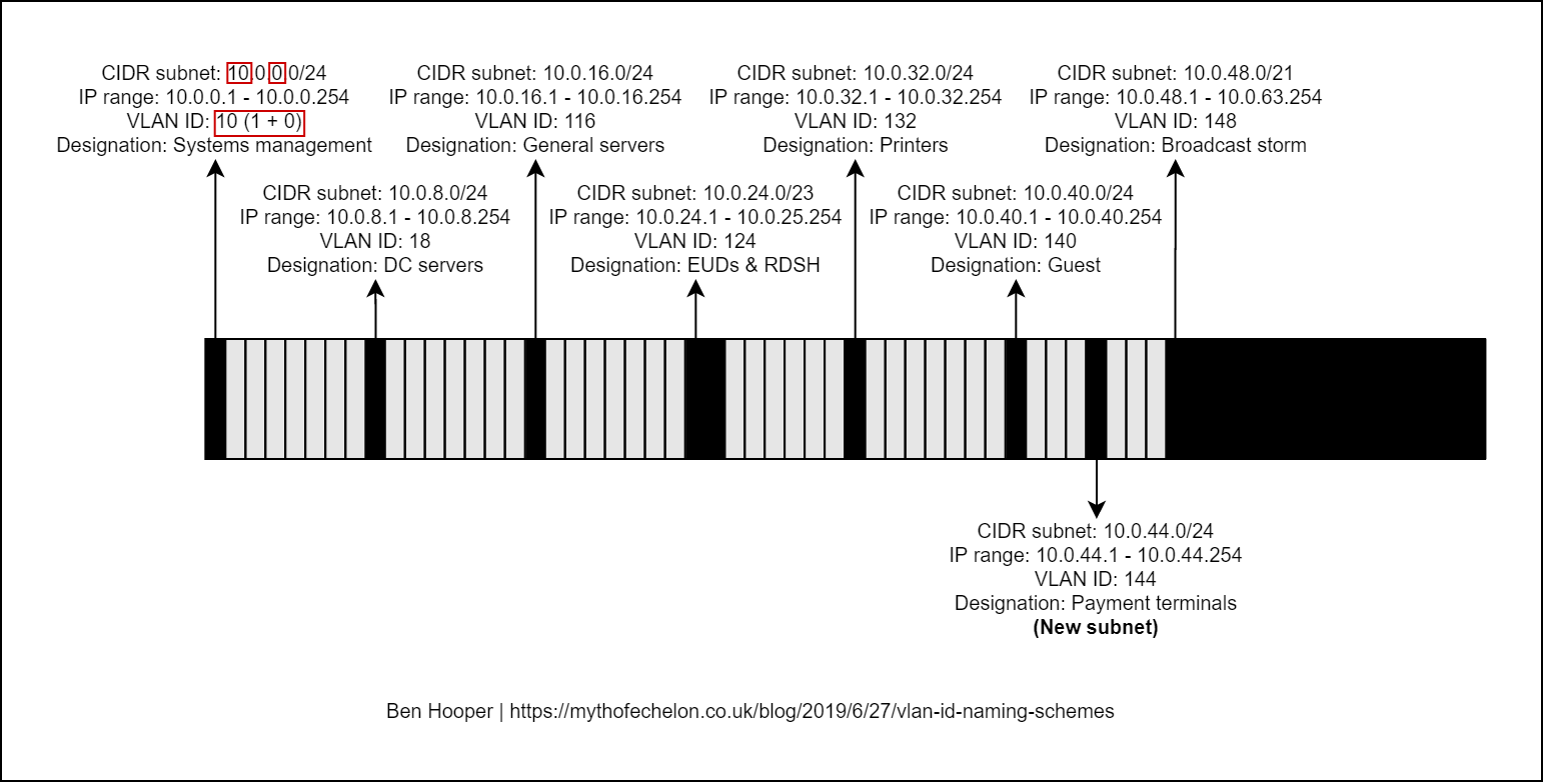
While we’re on the subject of schemes that are easy to get wrong, I thought I’d share my personal subnetting scheme. I like to use 10.<location>.<network type>.<host>/24 with the third octet starting at 0 and increasing by multiples of 8. For example:

  • 10.0.0.0/24

  • 10.0.8.0/24

  • 10.0.16.0/24

  • 10.0.232.0/24

  • 10.0.240.0/24

  • 10.0.248.0/24

The benefits of this are as follows:

  1. It’s scalable and an efficient use of IP space because the third octet being seperated by multiples of 8 means that, if needed, the existing subnets’ prefixes / masks can be expanded into the gaps or new subnets can be inserted.

  2. When combined with my preferred VLAN ID naming scheme, the VLAN IDs will be consistent across sites because VLANs are restricted to layer 2 networks. This is great for centrally-managed Wi-Fi / SSIDs, manually tagged devices, etc.

Some examples of network types that I would always try to segment are as follows:

  • Systems management such as Out-of-Band Management (OOBM) / Lights-Out Management (LOM), routers, firewalls, jumpboxes, etc.

  • Domain Controllers.

  • General servers.

  • Printers.

  • Organisation-owned End User Devices (EUDs) such as desktop PCs, laptop PCs, tablet PCs, smartphones, Remote Desktop Session Host (RDSH) servers, etc.

  • Personal-owned and guest devices.

  • Payment terminals.

    etc

Below, I have created a diagram as a visualisation of all of this:

View fullsize

Subnet diagram (2020-04-25 13-50).png

Content retrieved from: https://mythofechelon.co.uk/blog/2019/6/27/vlan-id-naming-schemes.

How To Set Up VLANs When You Don’t Understand VLANs

Several years ago, I needed to partition a network into separate VLANs.  The switches I had were capable, but I wasn’t.  I was having trouble understanding what the terms meant (Tagged, Untagged, Excluded) and how to configure each port to achieve my desired result.  I had trouble finding a good I-don’t-really-care-that-much-about-VLANS-or-Cisco-documentation-I-just-want-this-to-work-so-I-can-get-on-with-what-I-am-really-trying-to-do kind of explanation, so I thought I would write one.  Remember I said that was years ago?  My TODO list is very long.

The switches I was using in this project were Cisco/Linksys SGE2000P which is a “small business” switch.

VLAN concepts:

  1. VLANs are a way to group ports, potentially across multiple switches, into networks (Virtual Local Area Networks). In this way, a switch can be partitioned to, among other things, serve multiple networks all isolated from each other.
  2. Each VLAN is identified by an ID which is a number.
  3. Each port on the switch is designated as Tagged, Untagged or Excluded in each VLAN.
  4. If a port is Tagged, the switch will add the VLAN ID to the header of any packets sent on that interface.  Tagged packets are only understood by network equipment that is VLAN aware.
  5. If a port is Untagged the switch will not add the VLAN ID to the header of packets sent on that interface and will remove and VLAN IDs in packets that came in on a Tagged interface.
  6. If a port is Excluded from a VLAN packets with that VLAN ID will never be sent out on that port.
  7. If a port is marked Untagged on one VLAN, it will be excluded from all other VLANs.  In other words, an Untagged interface can only be a part of one VLAN at a time.
  8. A port can be marked as Tagged on any number of VLANs

What does all of that mean?

Any port that is going to carry traffic between 2 switches must be able to carry packets from all of the VLANs so therefore must be included in every VLAN that must transit that link.  The switch on the other end must be able to determine which VLAN to forward the packet to so the packets sent out that port must be tagged. It is also important that both switches understand VLANs.

Any port that is going to connect to a non-switch device must be marked untagged in the VLAN the device is supposed to be a part of.

Example

Say you want to create 3 different networks with 2 VLAN capable 16 port switches.  We’ll use VLAN IDs 7, 8, and 9.

We want to configure the networks thusly:

  • Connect port 16 on switch #1 to port 16 switch #2.  This cable will carry traffic from all 3 VLANs between the switches.  These ports must be tagged in all 3 VLANs
  • VLAN 7 will include ports 1, 2, and 3 on switch #1 and ports 1 and 2 on switch #2. These ports must be untagged on VLAN 7  and excluded from VLANs 8 and 9.
  • VLAN 8 will include ports 4 and 5 on switch #1 and ports 3, 4, and 5 on switch #2. These ports must be untagged on VLAN 8 and excluded from VLANs 7 and 9.
  • All other ports will be on VLAN 9. These ports must be untagged on VLAN 9 and excluded from VLANs 7 and 8.

So configure the ports like this:

Switch #1
Port VLAN 7 VLAN 8 VLAN 9
1 Untagged Excluded Excluded
2 Untagged Excluded Excluded
3 Untagged Excluded Excluded
4 Excluded Untagged Excluded
5 Excluded Untagged Excluded
6 Excluded Excluded Untagged
7 Excluded Excluded Untagged
8 Excluded Excluded Untagged
9 Excluded Excluded Untagged
10 Excluded Excluded Untagged
11 Excluded Excluded Untagged
12 Excluded Excluded Untagged
13 Excluded Excluded Untagged
14 Excluded Excluded Untagged
15 Excluded Excluded Untagged
16 Tagged Tagged Tagged


Switch #2
Port VLAN 7 VLAN 8 VLAN 9
1 Untagged Excluded Excluded
2 Untagged Excluded Excluded
3 Excluded Untagged Excluded
4 Excluded Untagged Excluded
5 Excluded Untagged Excluded
6 Excluded Excluded Untagged
7 Excluded Excluded Untagged
8 Excluded Excluded Untagged
9 Excluded Excluded Untagged
10 Excluded Excluded Untagged
11 Excluded Excluded Untagged
12 Excluded Excluded Untagged
13 Excluded Excluded Untagged
14 Excluded Excluded Untagged
15 Excluded Excluded Untagged
16 Tagged Tagged Tagged
 

Content retrieved from: https://www.megajason.com/2016/03/03/how-to-set-up-vlans-when-you-dont-understand-vlans/.

VMware iSCSI

Should I enable jumbo frames with iSCSI?

The general recommendation is to use the standard MTU of 1500 for iSCSI connectivity.

This recommendation is predicated upon several things:

  1. Simplicity. Enabling jumbo frames requires setting the proper MTU throughout the entire network. This means the vSphere Switch, vmkernel port (vmknic), physical NIC (pNIC), physical switches, routers (if routed iSCSI), and finally the FlashArray target ports. It is an all too common tale to see one or more of these components missed and thus problems with stability or performance are reported. 
  2. Not all environments benefit from jumbo frames. This was at one time a common (and rather heated) discussion in previous years. The anthem was almost always „jumbo frames enabled for best performance“. The reality though is actually based upon the workload between the initiators and target. If your applications / environment are consistently sending larger I/O requests than there is a good chance jumbo frames could help. How much will it help? Well, that answer can vary greatly so we won’t go into that here. The caveat though is that if the opposite is true (mostly smaller I/O requests), it can actually result in a performance penalty in your environment. If your host is waiting around to fill up a jumbo frame with smaller I/O requests then you are actually delaying transmission of your I/O and thus a slight performance penalty can be noted. How much? Again, it varies and isn’t the scope of this document.

The key takeaway here is know your environment. If you find jumbo frames are optimal for your environment please have all proper parties involved from end-to-end to ensure everything is implemented correctly.

If you decide to implement jumbo frames, the following command is vital to ensure you have properly configured your environment end-to-end:

vmkping -I <iscsi_vmk_interface> -d -s 8972 <ip_addr_of_target>

This ensures packets are not fragmented during the ping test (-d) and tests jumbo frames (-s 8972).

HP / Aruba Procurve 2530/2500 Default Management IP, Username/Passwrods and Configurations

HP / Aruba Procurve 2530/2500 Default Management IP, Username/Passwrods and Configurations

Back-up of an existing config

If you are performing a backup a config from another switch, two ways of downloading the configuration is through GUI and CLI (via TFTP)

via GUI: (System -> Updates/Download -> Configuration File (Highlight config name and click Download)

2018-02-20 16_47_16-HP 2530-24G-PoEP Switch (J9773A).png

via CLI. (you need to set up a TFTP server on a machine)

switch# copy running-config tftp <IP Address of the TFTP Server> filename.pcc

==============
Default Settings and Configurations of an Aruba/HP Procurve switch

In the factory default configuration, the switch has no IP (Internet Protocol) address and subnet mask, and no passwords. In this state, it can be managed only through a direct CONSOLE connection (How to connect to Console? Click here). To manage the switch through inband (networked) access, you should configure the switch with an IP address and subnet mask compatible with your network. Also, you should configure a Manager password to control access privileges from the console and Web browser interface.

IP-Address

HP ProCurve Switch 2524# configure
HP ProCurve Switch 2524(config)# vlan 1
HP ProCurve Switch 2524(vlan-1)# ip address 10.0.0.1 255.255.255.0
HP ProCurve Switch 2524(vlan-1)# wr mem
HP ProCurve Switch 2524(vlan-1)# exit
HP ProCurve Switch 2524(config)# exit
HP ProCurve Switch 2524#

(Basically, from here you can now set your machine’s IP into the same network above and access the GUI from your browser, otherwise, you can proceed with the other commands below)

Also, by default, as mentioned there is no username/password for the switch and you have to configure that manually through GUi or CLI below.

Configure VLANs

HP ProCurve Switch 2524# configure
HP ProCurve Switch 2524(config)# vlan 1
HP ProCurve Switch 2524(vlan-1)# name „Default“
HP ProCurve Switch 2524(vlan-1)# untag 2-6
HP ProCurve Switch 2524(vlan-1)# vlan 10
HP ProCurve Switch 2524(vlan-10)# name „First“
HP ProCurve Switch 2524(vlan-10)# untag 7-12
HP ProCurve Switch 2524(vlan-10)# vlan 20
HP ProCurve Switch 2524(vlan-20)# name „Second“
HP ProCurve Switch 2524(vlan-20)# untag 13-18
HP ProCurve Switch 2524(vlan-20)# exit
HP ProCurve Switch 2524(config)# exit
HP ProCurve Switch 2524#

Set up trunk ports

HP ProCurve Switch 2524# config
HP ProCurve Switch 2524(config)# trunk 23-24 trk1
HP ProCurve Switch 2524(config)# vlan 10
HP ProCurve Switch 2524(vlan-10)# tagged trk1
HP ProCurve Switch 2524(vlan-10)# vlan 20
HP ProCurve Switch 2524(vlan-20)# tagged trk1
HP ProCurve Switch 2524(vlan-20)# wr mem
HP ProCurve Switch 2524(vlan-20)# exit
HP ProCurve Switch 2524(config)# exit
HP ProCurve Switch 2524#

Disable all (but trunk) ports

HP ProCurve Switch 2524# configure
HP ProCurve Switch 2524(config)# int 2-22 disable
HP ProCurve Switch 2524(config)# wr mem
HP ProCurve Switch 2524(config)# exit
HP ProCurve Switch 2524#

Enable only necessary ports

HP ProCurve Switch 2524# configure
HP ProCurve Switch 2524(config)# int 2-4 enable
HP ProCurve Switch 2524(config)# int 13-15 enable
HP ProCurve Switch 2524(config)# wr mem
HP ProCurve Switch 2524(config)# exit
HP ProCurve Switch 2524#

Set up speed etc.

HP ProCurve Switch 2524# configure
HP ProCurve Switch 2524(config)# int 2-4 speed-duplex 100-full
HP ProCurve Switch 2524(config)# int 13-15 speed-duplex auto
HP ProCurve Switch 2524(config)# wr mem
HP ProCurve Switch 2524(config)# exit
HP ProCurve Switch 2524#

Set time and date

Time and date on hh:mm and mm:dd:yyyy format

HP ProCurve Switch 2524# configure
HP ProCurve Switch 2524(config)# time 10:05
Mon Jan 1 10:05:28 1990
HP ProCurve Switch 2524(config)# time 08/24/2010
Tue Aug 24 10:05:41 2010
HP ProCurve Switch 2524(config)# wr mem
HP ProCurve Switch 2524(config)# exit
HP ProCurve Switch 2524#

Set hostname

HP ProCurve Switch 2524# configure
HP ProCurve Switch 2524(config)# hostname „ServerRoom1“
ServerRoom1(config)# wr mem
ServerRoom1(config)# exit
ServerRoom1#

Backup settings

After running “sh run” copy/paste all between line which start with “hostname” to “ServerRoom1#” example to notepad and save that file.

ServerRoom1# sh run
ServerRoom1#

Restore settings from backup

All you have to do is copy/paste all (except the first “Running configuration:” line) to notepad on “Backup settings” part to “HP ProCurve Switch 2524#”.
If you have set operator and/or manager passwords, don’t copy/paste the lines which start with password.

HP ProCurve Switch 2524# configure
HP ProCurve Switch 2524(config)#

Set manager and operator password

ServerRoom1# configure
ServerRoom1(config)# password all
New password for Operator: ********
Please retype new password for Operator: ********
New password for Manager: ********
Please retype new password for Manager: ********
ServerRoom1(config)#

Content retrieved from: https://marktugbo.com/2018/02/20/hp-aruba-procurve-2530-2500-default-configurations/.

Betrieben von WordPress | Theme: Baskerville 2 von Anders Noren.

Nach oben ↑